
* If button not pushed then stop the vibration motor */ * The waveform library has 0-122 different types of waves */ * This outputs to log that button has been pressed, use for debugginh */ Library( 2) //1-5 & 7 for ERM motors, 6 for LRA motors

MotorSelect( 0x36) // ERM motor, 4x Braking, Medium loop gain, 1.365x back EMF gain Mode( 0) // Internal trigger input mode - Must use the GO() function to trigger playback.
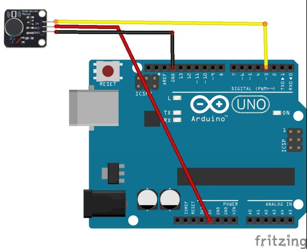
VIBRATION MOTOR ARDUINO CIRCUIT DRIVER
* Initialize Haptic Motor Driver Object */ Int button_val = 0 // variable for reading the pin status Int button = 7 // choose the input pin 7 for pushbutton SFE_HMD_DRV2605L HMD //Create haptic motor driver object # include //SparkFun Haptic Motor Driver Library Step 9: Plug in the Arduino and upload the code, and watch it work! Step 8: Connect a final write from SIG on the button breakout to a pin on the Arduino (for the purposes of our code, we used pin 7). Use another jumper wire to connect the GRD from the 4 pin jumper wire connected to the button breakout to the same row as the other GRD wires on the breadboard. Step 7: Now we will finish up by connecting the button to the vibration motor driver and Arduino. Do the same for the SCL row on the breadboard to the SCL pin on the motor driver. Then run a wire from the row where the SDA pin is connected on the breadboard to the SDA pin on the motor driver. Alternatively, follow a similar approach to step 5 and connect the SDA and SCL pins on the Arduino to their own rows on the breadboard via jumper wires. Again, do the same with the SCL pins on both. Step 6: Use yet another wire to connect the SDA pin on the vibration motor driver to the SDA pin directly on the Arduino. Do the same with another wire for VCC (volt) on the vibration motor driver, to the volt row of the breadboard. Using a third jumper wire, connect the GND pin on the vibration motor driver to the same row on the breadboard as the GRD pin from the Arduino. Step 5: Now we will connect the vibration motor driver to the Arduino. Step 4: Using another jumper wire, connect the Volt 3.3 pin on the Arduino to a different row on the breadboard. Step 3: Using one of the jumper wires, connect the GRD pin on the Arduino to a row on the breadboard. Step 2: Connect the 4 pin jumper cable to the button breakout. Solder the wires of the coin vibrator into the terminals of the vibration motor driver. Step 1: Solder the edge connector to the vibration motor driver.


 0 kommentar(er)
